
Ground Protection Mats for Wind Farms: Panel Counts, Turbine-to-Turbine Reuse and the Outrigger Boundary
For wind farm access roads and staging, start with 20 mm HDPE panels on a prepared subgrade, connected and staggered, and rotate one panel set across turbine positions. Crane outriggers and crawler-crane hardstands need a separate engineered point-load calculation; no published tonnage covers a lift plan. Voids, deep peat and sustained steel tracks are outside scope.
This page covers the access system and construction sequence, not the board as a product. For the panels see 4×8 ft ground protection mats and standard specifications; for road geometry see temporary access roads.
What wind farm ground protection mats are
Each standard panel is 1,220 × 2,440 mm, covers 2.98 m², carries a dual-face tread and has four hand holes and eight connector holes. Connected edge to edge, panels form a removable load-spreading layer that transfers wheel loads into the soil over a larger footprint than a tyre contact patch. On a wind site that layer has three jobs, and only one belongs to a standard HDPE panel: the access track to each turbine position, staging and laydown near the foundation, and the crane hardstand and lift itself — a point-load problem a ground protection mat does not solve. Conflating the three is the most expensive specification error here: a bill of quantities listing only “mats” omits the hardstand, swept-path widening and rotation logistics.
A typical onshore fleet includes extendable blade trailers, tower-section haulers, ballast tractors, concrete mixers and a crawler crane in the hundreds-of-tonnes class. These are industry reference ranges for planning, not our test data; take the actual fleet from the transport contractor and the lift plan. The design case is the heaviest axle group at the worst ground condition, and a crawler crane travels on steel tracks — a material problem, not a thickness problem. wind farm access mats names the product; the arrangement is the track, widening, subgrade, joints, hardstand and reuse schedule.
When to use them on a wind site — and when not to
| Condition | Suitable | Notes |
|---|---|---|
| Project duration | 6–24 months per phase | Long enough that reuse across positions pays back |
| Traffic | Repeated laden passes by rubber-tyred haulage and ballast tractors | Count passes, not vehicles |
| Ground | Firm granular soil to soft clay and drained peat, provided it can be separated | Peat requires a geotechnical assessment and derating |
| Gradient | Gentle, substantially level running surface | Steep grades add braking shear at the joints |
| Reinstatement | Agricultural or moorland ground to be returned to original condition | Panels leave no aggregate to remove |
| Access constraint | Remote site, narrow easements, long haul from the compound | Despatch sequence matters as much as panel count |
| Programme | Several turbine positions built in sequence | One rotating fleet is the economic unit |
Do not use a standard HDPE panel when:
- The position is a crane outrigger, crawler-crane hardstand or any lift-plan location. Obtain a site-specific engineering assessment and the platform it specifies.
- Sustained steel-track traffic is expected — crawler-crane grousers cut HDPE; evaluate composite, timber or steel instead.
- The panels would bridge a void, trench, culvert or ditch. Panels are load spreaders, not beams.
- The subgrade is deep, unbounded peat or silt with no bearing layer. Mats migrate regardless of thickness.
- The road is permanent, carries public traffic, or must meet a highway specification without further assessment.
- A permit or lift plan requires certified design values. Our published figures are not certified design values.
Stating these limits is the first thing a heavy-lift coordinator checks when judging a supplier.
How to install and use them: road layout, swept paths and a 7-step sequence
Road width, swept-path widening and panel count per km
A panel laid with its 2,440 mm edge across the direction of travel gives a 2.44 m single lane. A blade transporter is not ordinary one-way plant: a blade tens of metres long on an extendable trailer has a large turning circle, its rear wheels track inside the front wheels, and the blade tail sweeps outside the bend. As a typical guideline, illustrative and not a design value, widen bends by one to two panel widths on the outside and add a laydown bay wherever a delivery queues. The transport contractor’s swept-path analysis governs. The take-off below is an illustrative quantity calculation, not a design value.
| Step | Basis | Result |
|---|---|---|
| Straight single lane, 2.44 m | 1,000 m ÷ 1.22 m coverage per panel | 820 panels/km |
| Staggered joints | Half-panel offset; no change to count | 820 + ~20 half-width end panels |
| Passing / blade-laydown bays | One bay per 250 m, ~12 m × 4.88 m | +~32 |
| Swept-path widening at bends | 6 bends × 2 extra outer rows | +~72 |
| Non-lift hardstand approach apron | 15 m × 4.88 m per position | +~60 |
| Order quantity per km | 820 + ~164 allowance | ≈ 1,000 panels/km |
| Two-way blade route, 4.88 m | Double the straight run before allowances | ≈ 1,640 + allowances |
Stagger joints by half a panel so no continuous seam sits under a wheel path; a straight seam opens under braking. Avoid field cutting: our custom and listed sizes include 610 × 2,440 mm panels that close alternating rows cleanly. Published industry reference ranges put a 40 ft high-cube at roughly 300–350 panels at 20 mm and 200–250 at 30 mm, to be confirmed against actual stack height and packing method.
Turbine-to-turbine reuse: rotation and amortisation
This is the calculation a wind EPC actually needs. Assume a 20-position site, each with a 250 m spur: 250 ÷ 1.22 ≈ 205 panels, plus 15% gives a 240-panel set. Build one set, recover it, and move it to the next position as each turbine is commissioned.
| Programme week | Turbine position | Spur laid | Panels deployed | Recovered from previous | Net fleet in circulation | Cumulative deployments per panel |
|---|---|---|---|---|---|---|
| 1 | T01 | 250 m | 240 | — | 240 | 1 |
| 3 | T02 | 250 m | 240 | 240 (T01) | 240 | 2 |
| 5 | T03 | 250 m | 240 | 240 (T02) | 240 | 3 |
| 7 | T04 | 250 m | 240 | 240 (T03) | 240 | 4 |
| … | … | … | … | … | … | … |
| 39 | T20 | 250 m | 240 | 240 (T19) | 240 | 20 |
| Scenario | Panels purchased | Panel-deployments delivered | Uses per panel | Relative panel spend | Storage and handling |
|---|---|---|---|---|---|
| Buy every spur up front | 4,800 | 4,800 | 1 | 100% (baseline) | 4,800 panels staged on a remote site |
| One rotating fleet, 20 positions | 240 | 4,800 | 20 | 5% of baseline | Recover, wash, inspect, haul to next position |
| Two fleets, 10 positions each | 480 | 4,800 | 10 | 10% of baseline | Two parallel work faces, buffer stock |
Illustrative cost model, not a quotation or a design value. Substitute your own panel price, recovery labour, haul distances and loss rate. If recovery slips, the next position waits — give the rotation the same programme status as the crane booking.
The 7-step sequence
- Walk and zone the route. Mark soft hollows, peat, springs, buried cables and transitions; obtain the swept-path drawing first.
- Drain before you lay. Cut intercept drains or pump standing water on exposed upland sites.
- Roll out geotextile and pin it against wind, with generous seam overlaps.
- Start on firm ground and work outward. Every first-row panel needs full support; never span a hollow.
- Stagger, orient the tread, connect every panel — vehicle tread up; use the connection system for braking and turning shear.
- Run one laden vehicle at walking pace, then re-inspect for edge settlement, joint opening and migration; repeat at the bends on the first blade delivery.
- Recover from the far end backwards as each position is commissioned: wash, inspect hand holes and connectors, stack flat, release the set to the next turbine.
The full handling and recovery procedure is in how to install ground protection mats.
What they save: why reuse across turbine positions dominates the TCO
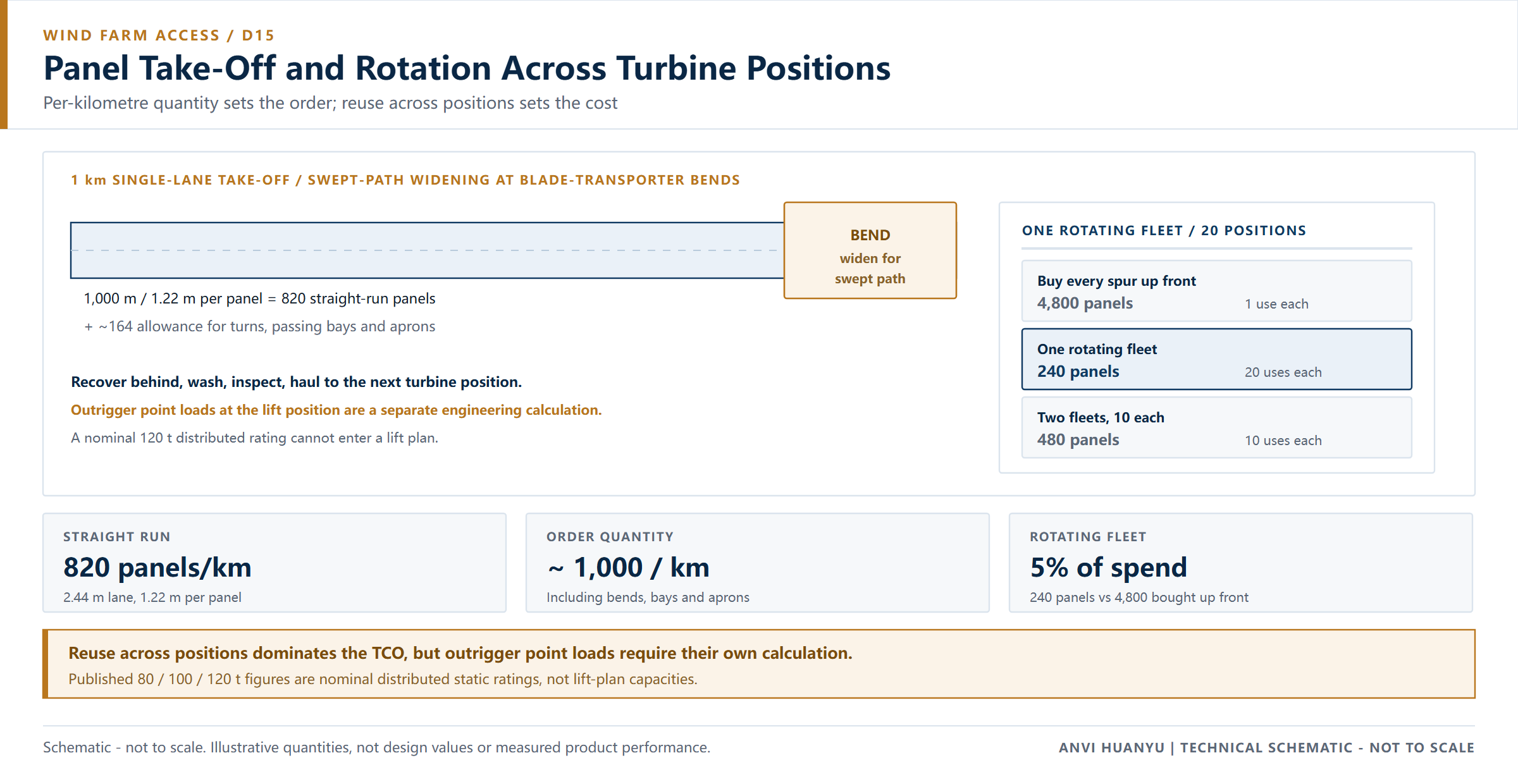
The honest comparison is one rotating fleet versus twenty separately built stone spurs. For one 250 m × 4.88 m spur, a 300 mm aggregate layer needs roughly 366 m³ of stone, about 586 t at 1.6 t/m³, or 24–29 lorry deliveries — across twenty positions, 500–580 movements, before excavating, removing and disposing of the stone and restoring peat or farmland at handover. On peat, aggregate punches into the subgrade and is largely unrecoverable.
| Cost line | Stone spur per turbine position | One rotating HDPE fleet |
|---|---|---|
| Material movements | 24–29 lorry loads per position; ~500–580 across the site | One container delivered once, then site hauls |
| Reinstatement | Excavate, remove, dispose, restore topsoil | Lift, wash, store |
| Programme | Each spur built before its crane arrives | Set available for the next position in days |
| Peat and soft ground | Aggregate lost into the subgrade | Drain, geotextile, derate; no imported stone |
| Failure cost | Regrade and re-deliver stone | Re-lay affected panels after inspection |
Use this framework with your own day rates:
Cost per deployment = (delivered cost + deployment labour + recovery + washing
 + inter-position haul + losses + reinstatement) ÷ rotations
The break-even depends on how many times the same set is redeployed; our cost and ROI guide sets out the model. For one short project, hiring from a rental fleet may beat buying. Sequence containers to the lift programme, and require a written packing list, stacking plan and despatch dates before the order is released.
Why these mats — not a lighter panel or another material
| Option | Where it fits on a wind site | Why we would not choose it here |
|---|---|---|
| 12.7 mm HDPE | Pedestrian routes, turf protection, finished surfaces | Under repeated heavy axles the board deflects; joints loosen and edges lift |
| 15 mm HDPE | Light service vehicles on firm ground, short works | Marginal for continuous laden haulage on variable ground |
| 20 mm HDPE (recommended for roads) | Access tracks, staging, repeated dynamic loading | Practical ceiling for standard panels — not a lift-pad rating |
| 25–30 mm+ HDPE / composite | Engineered heavy-lift or extreme soft-ground cases | Heavier, fewer per container, still no substitute for a lift-plan calculation |
| Timber bog mats | Very soft peat, one-off heavy access | Absorbs water, gains weight, can carry seed, harder to clean between positions |
| Steel plates / engineered crane mats | Crane hardstands, critical lifts | Correct for point loads; needs lifting plant, corrodes, conductive; see HDPE vs steel mats |
| Plywood | Nothing on a haul route | Delaminates and swells; see HDPE vs plywood mats |
- Why not the cheaper, thinner board? On a remote site the cost is not the panel, it is the crane waiting. A working joint under a braking ballast tractor delays a lift — illustrative reasoning, not a quotation.
- Why not simply the thickest board? Beyond 20 mm, weight, handling and container utilisation deteriorate, and extra stiffness will not fix an unprepared peat subgrade or turn a distributed rating into a point-load rating.
Four hand holes and eight connector holes let linked panels resist the shear that pushes loose boards apart on bends; a mixed-thickness field does not sit flat.
Why 20 mm for the road, and why outrigger point loads are a separate calculation
The figures below are an illustrative engineering check, not a certified design value.
Heaviest axle group → tyre / track contact pressure → spread over the panel
→ subgrade derating → 15–20% margin → 20 mm road conclusion (starting point)| Step | What to establish | Illustrative check |
|---|---|---|
| 1 | Heaviest vehicle on the track | Blade transporter combination, rear axle group ≈ 30 t (assumed for this example) |
| 2 | Contact pressure | Concentrated at the patch; the panel’s job is to spread it |
| 3 | Ideal spread over one panel | 30,000 kg × 9.81 ÷ 2.98 m² ≈ 99 kPa if the whole board acted as a rigid plate |
| 4 | Real effective area | HDPE deflects between supports, so at 60% effective area ≈ 165 kPa |
| 5 | Subgrade allowance | Dry compacted granular tolerates this; saturated clay and peat often do not (industry guidance: saturated soil loses 30–50% of dry bearing capacity, saturated clay −25~35%, peat up to −50%) |
| 6 | Safety margin | Add 15–20%; specify against the heaviest machine, never the fleet average |
| 7 | Conclusion | 20 mm on prepared ground; geotextile and, on wet clay, a double layer in the wheel paths |
The lift is a different calculation. A crawler crane or mobile crane outrigger applies a point load, not an evenly distributed one. Required bearing area is A = outrigger reaction ÷ allowable ground bearing pressure (illustrative calculation, not a design value), and the panel must be checked for bending between supports, not just crushing. Our published reference ratings — 80 / 100 / 120 t for 12.7 / 15 / 20 mm — are nominal figures for evenly distributed static loading on a firm, level subgrade. They are not certified design values and must not be used as point-load capacity, crane outrigger capacity, or a permit-to-bridge voids. We publish no test method, sample thickness, support span or test report for these figures; they are labels, not design inputs. No thickness on this page, including 20 mm, covers a lift plan. A method statement citing “120 t mats” for a crane hardstand is wrong and, on an insured project, likely to be rejected. Where a lift plan or permit applies, obtain a site-specific engineering assessment.
Three qualifications belong in any specification written from this table:
- We have not used our published nominal ratings in the calculation above — they describe a distributed static case, not a wind-site lift.
- Confirm the thickness convention: base sheet or overall including raised tread on both faces. The difference can approach 10 mm and changes stiffness, stacking height and edge ramps. See how to choose ground mat thickness.
- Thickness changes freight: at 30 mm the same container carries materially fewer panels (industry reference range, to be confirmed against actual stack height and packing method).
This is a selection starting point, not a certified design value. Confirm against the heaviest machine on site, not the fleet average. Common mis-specifications: choosing by average vehicle weight; treating a nominal tonnage as permission for a lift; buying thicker boards instead of fixing drainage; omitting swept-path widening.
Common failure modes on a wind farm access route
| Failure | What it looks like | Cause | Prevention |
|---|---|---|---|
| Edge settlement on a bend | Outer panel drops, trailer tyre off the edge | No swept-path widening | Add outer rows from the swept-path drawing |
| Steel-track cutting | Grouser gouges in the running surface | Crawler crane travelling on HDPE | Change material at crane positions; engineering sign-off |
| Outrigger punch-through | Hardstand settles during a lift | Nominal tonnage used as point-load capacity | Engineered point-load calculation and platform |
| Panel migration in peat | Whole field creeps in the direction of travel | No bearing layer, no geotextile | Drain, separate, double wheel paths, ground improvement |
| Joint opening under braking | Visible gap along a continuous seam | Unstaggered seams, braking shear | Half-panel stagger; appropriate connectors |
| Programme gap | Panels arrive after the crane | Single bulk despatch, no rotation plan | Despatch schedule tied to the lift sequence |
| Seed or soil transfer | Vegetation at the next position | Skipped wash-down | Pressure-wash and inspect before redeployment |
These are sequence failures, not product failures.
What to verify with any supplier before you buy
Before a panel quantity becomes a purchase order, ask every bidder — including us — the same eight questions.
- Is the published load figure static, dynamic, distributed or point, and what were the sample thickness and support span? Will the supplier state in writing that it is not an outrigger or lift-plan value?
- Is the quoted thickness the base sheet or overall including tread?
- What crew or plant places panels at a remote turbine position, and can the same set be recovered? Trial it with a sample panel at the first position.
- What is the thickness tolerance and how is batch consistency recorded?
- What is the material declaration — virgin HDPE, regrind or PCR, and UV stabilisation — for a 12–24 month programme?
- What connectors are supplied, and are they compatible across thicknesses and future orders under braking and turning shear?
- Can the supplier provide a loading plan — panels per 40HQ at 20 mm, stack height, and how despatch maps to the turbine order?
- Can the supplier provide a test report with an identifiable method and issuing laboratory?
For a wind programme the useful question is whether what you see being loaded can be turned into a written packing list and a despatch sequence across twenty turbine positions. We can supply dated working photographs of our line, a thickness check and the loading operation with a quotation. Use them to understand the loading method; the container quantity, stacking plan, tier split and dated milestones must come as documents, and a photograph is not a delivery commitment.
Specification summary for a wind farm access road
| Item | Starting specification |
|---|---|
| Panel | 1,220 × 2,440 mm HDPE, 4 hand holes + 8 connector holes, dual-face tread |
| Thickness | 20 mm for access roads and non-lift staging (confirm base-sheet vs overall) |
| Lane width | 2,440 mm minimum single lane; widen at bends for the blade-transporter swept path |
| Quantity | ≈ 1,000 panels per km including turns, bays and aprons (worked example) |
| Fleet strategy | One rotating set across N turbine positions; recover, wash, inspect, redeploy |
| Joint pattern | Half-panel stagger; listed 610 × 2,440 mm panels at row ends |
| Connections | Every panel; type selected for braking and turning shear |
| Subgrade | Drained, geotextile separation; peat requires derating and ground improvement |
| Crane / outrigger | EXCLUDED — separate engineered point-load calculation and lift plan |
| Exclusions | No void spanning, no sustained steel tracks, no permanent roads, no certified lift pads |
| Reference ratings | 80 / 100 / 120 t nominal for 12.7 / 15 / 20 mm, distributed static on firm level ground — not certified design values; no test basis published, not for design use |
Frequently asked questions
How many mats for a 1 km turbine access road? For a 2.44 m single lane, 1,000 m ÷ 1.22 m ≈ 820 panels. Add roughly 20% for end panels, bays, swept-path widening and the hardstand approach — about 1,000 panels per km. A two-way blade route roughly doubles the straight run. This is an illustrative take-off; the swept-path drawing governs the bends.
What thickness for a crawler crane at a turbine base? No thickness on this page covers it. An outrigger applies a point load, and bearing area must be calculated from the outrigger reaction and allowable ground pressure. Our 80 / 100 / 120 t figures are nominal distributed static ratings, not certified design values and not lift-plan values. Where a lift plan or permit applies, obtain a site-specific engineering assessment.
Can mats be reused across turbine positions? Yes — it is the strongest cost argument here. In the worked example a 240-panel set reaches twenty uses per panel instead of buying 4,800 panels. Write recovery into the programme: wash, inspect, count back in, store flat, release on schedule.
Do blade transporters need a wider mat road? Yes. A long blade sweeps outside the bend while its rear wheels track inside the front wheels. As a typical guideline, illustrative and not a design value, widen bends by one to two panel widths on the outside. The transport contractor’s swept-path analysis controls.
Are HDPE mats suitable for crane walkways or hardstands? Not as a rated lift platform. Crawler cranes travel on steel tracks, which cut HDPE, and a hardstand is a point-load problem. Evaluate composite, timber or steel with engineering sign-off, and keep HDPE for the access road and non-lift staging.
How should containers be sequenced for a remote wind site? Tie despatch to the lift sequence, not one bulk shipment. Ask for a written packing list, stacking plan, loading quantity per 40HQ and dated milestones. Loading photographs are context, not a container quantity, tolerance or delivery commitment.
Get a thickness and panel count for your site
Send the equipment tonnage and axle groups, the ground or geotechnical condition, the construction duration, the number of turbine positions and the target panel quantity. We will return a recommended thickness with its basis, a panel count per km, a rotation and despatch plan, and a container estimate — to albert@hdpegroundmat.com or via our contact page.