
Ground Protection Mats for Solar Farms: Mobile Access Roads, Phased Reuse and Desert Sand Control
For solar panel delivery routes and pile-driving plant on firm ground, 12.7–15 mm HDPE panels are sufficient; buy a rolling set that advances with the installation front rather than a full-length road. Use 20 mm only on soft clay or at transformer and crane zones. Desert sand needs anchoring, not extra thickness; permanent roads, lift pads and unbounded peat are outside scope.
This page is about a moving work front, not a fixed haul road. For blade transporters and crawler-crane lifts, see ground protection mats for wind farms; for continuous-traffic geometry see temporary access roads.
What solar farm ground protection mats are
A solar access system is a recoverable running surface laid in a short active window so module trucks, telehandlers and pile-driving rigs can reach the installation front without permanent roads. Each standard panel is 1,220 × 2,440 mm, covers 2.98 m², has a dual-face tread, four hand holes and eight connector holes. Panels are connected, recovered behind the front and re-laid ahead — the same boards, moved many times.
The PV fleet is light-to-medium: 18–26 t module trucks, telehandlers, 12–20 t rubber-tracked pile drivers and an occasional 40 t BESS or transformer delivery — industry reference planning ranges, illustrative and not a design value. Axle loads are moderate, but the area is very large: a utility-scale site covers square kilometres of pile rows, with only a narrow strip active at once. A large-area, low-load zone justifies neither a site-wide pavement nor a heavy panel everywhere.
Paving every row is uneconomic, and a continuous mat road ties up capital in idle boards. The arrangement is a rolling carpet: a fixed set of panels covering 150–250 m of spine road plus row spurs, advanced in steps with the crews. The engineering problems are repetitive handling, sand migration and keeping deliveries running through wet weather — not an extreme axle. The arrangement adds the advance step, recovery log, sand anchoring and a small heavier-panel reserve.
When to use them on a PV site — and when not to
| Condition | Suitable | Notes |
|---|---|---|
| Project duration | 3–12 months, installed in phases | Long enough for many advance cycles to pay back |
| Traffic | Repeated light-to-medium rubber-tyred deliveries and rubber-tracked pile rigs | Count passes per phase |
| Ground | Firm granular soil, damp sand, desert crust over a competent layer | Sand needs anchoring; soft clay needs geotextile and 20 mm |
| Gradient | Substantially level array blocks | Steep grades add braking shear at joints |
| Reinstatement | Farmland, pasture or desert surface returned to original condition | Panels leave no aggregate to remove |
| Area | Large, low-load array with a narrow active front | A rolling set, not a full-length road |
| Weather | Deliveries must continue through a wet season | Surface stays intact; the subgrade still governs |
| Crew | Two-person handling preferred; limited lifting plant | Handling method is a primary selection variable |
Do not use a standard HDPE panel when:
- The location is a transformer, inverter or BESS skid placement, or any crane lift — a point-load problem; 20 mm panels are not a rated lift pad. Obtain a site-specific engineering assessment.
- The road is permanent, carries public traffic, or must meet a highway specification without further assessment.
- The ground is deep, unbounded peat, standing water, flowing water or subject to scour. Anchoring does not create bearing capacity.
- The panels would bridge a void, trench, culvert or irrigation canal. Panels are load spreaders, not beams.
- Sustained steel-track traffic is expected — grousers cut HDPE; evaluate composite, timber or steel.
- A permit requires certified design values; our published ratings are not.
- The same set cannot be cleaned between catchments where a biosecurity rule applies.
20 mm at the transformer compound is not a lift platform.
How to install and use them: phased advance with the installation front
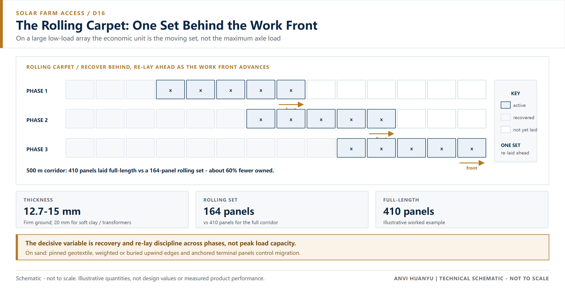
The rolling carpet: recover behind, re-lay ahead
Divide a 500 m corridor into a 200 m active window: at 1.22 m coverage per panel that needs 200 ÷ 1.22 ≈ 164 panels for a 2.44 m lane. Each phase the front advances 50 m: recover the rearmost 41 panels, wash, truck forward and re-lay ahead. The set stays at 164; the road never exists as a 500 m field. Illustrative take-off, not a design value.
| Phase | Active window | Work front at | Recovered at rear | Re-laid ahead | Rolling set | Distinct panels owned | Full-length alternative |
|---|---|---|---|---|---|---|---|
| 1 | 0–200 m | 200 m | 0 | 164 (initial lay) | 164 | 164 | 410 |
| 2 | 50–250 m | 250 m | 41 | 41 | 164 | 164 | 410 |
| 3 | 100–300 m | 300 m | 41 | 41 | 164 | 164 | 410 |
| 4 | 150–350 m | 350 m | 41 | 41 | 164 | 164 | 410 |
| 5 | 200–400 m | 400 m | 41 | 41 | 164 | 164 | 410 |
| 6 | 250–450 m | 450 m | 41 | 41 | 164 | 164 | 410 |
| 7 | 300–500 m | 500 m | 41 | 41 | 164 | 164 | 410 |
A continuous 500 m road takes 500 ÷ 1.22 ≈ 410 panels; the rolling set holds 164 — about 60% fewer. A loss allowance per rotation is a sensible planning assumption (typical guideline, illustrative, not a measured figure); we publish no measured loss rate; treat it as a project-specific allowance.
Sand and soft-soil anchoring and displacement control
Desert sand migration is the sector-specific failure: wind scours sand from beneath edges, panels drift under turning, and cohesionless sand gives geotextile nothing to grip. The answer is anchoring and inspection, not a thicker board — weight or bury the upwind edge, pin the geotextile, anchor terminal panels, avoid spin turns, probe beneath edges after the first windy night. These are typical guidelines, illustrative and not a design value; a geotechnical assessment governs.
| Ground condition | Migration mechanism | Control measure | Site check | Escalate to 20 mm + geotextile when |
|---|---|---|---|---|
| Dry desert sand, windy | Wind scours from under edges; panels shift laterally | Weight or bury the upwind edge, pin geotextile, anchor terminal panels | Probe under edges after one windy night | Loose sand extends beyond 300 mm with no crust |
| Damp sand / sandy silt | Fines pump into joints, ruts form under repeated passes | Geotextile separation, widened wheel paths, no spin turns | Rut depth after one laden truck | Rut exceeds 50 mm under a laden pass |
| Firm clay / compacted granular | Low migration | Standard staggered lay, connect every panel | Joint opening check after first pass | Sustained rain saturates the surface |
| Soft clay at the transformer compound | Edge settlement under skid deliveries | 20 mm, geotextile, doubled wheel paths, engineered platform for the lift | Settlement survey before skid placement | Any lift plan or skid placement applies |
| Salt-flat or crust over a soft layer | Crust punches through | Establish crust thickness; avoid concentrated turning | Proof roll with one laden vehicle | Crust is thinner than 150 mm (illustrative screening) |
Indicative site-practice matrix from industry reference ranges; not a design value. A geotechnical assessment governs.
The 7-step sequence
- Walk and zone the corridor. Mark soft hollows, irrigation, buried cables, desert crust, the field gate and firm-ground transitions; fix the advance step first.
- Prepare the surface. On sand, cut off wind-blown drift; on fine soil, drain and roll out geotextile. Never lay over standing water.
- Anchor the separation layer against wind; an unanchored layer lifts and bunches under the first turning truck.
- Start on firm ground and build outward. Every first-row panel needs full support; never span a hollow.
- Stagger, orient the tread, connect every panel. Vehicle tread up on delivery routes; use the connection system rated for repeated make-and-break, and close row ends with listed custom sizes rather than cutting on site.
- Run one laden module truck at walking pace, then re-inspect for edge scour, joint opening and drift; repeat after the first windy night.
- Recover behind, inspect, wash, re-lay ahead. Count the set back in, note connector replacements, update the rotation log.
The full handling and recovery procedure is in how to install ground protection mats.
What they save: cost per use as the work front moves
The comparison has three columns: gravel road, full-length mat road, rolling set. For 500 m × 2.44 m, a 200 mm aggregate layer needs roughly 244 m³ of stone, about 390 t at 1.6 t/m³, or 16–20 lorry loads — before grading and removing and disposing of the stone at handover. A full-length mat road still buys 410 panels; the rolling set buys 164 and uses them seven times.
| Factor | Full-length gravel road | Full-length 410-panel mat road | 164-panel rolling set |
|---|---|---|---|
| Material bought | ~244 m³ stone | 410 panels | 164 panels |
| Road present at once | 500 m | 500 m | 200 m active window |
| Reinstatement | Excavate, remove, dispose, restore | Lift, wash | Lift, wash, re-lay ahead |
| Wet-weather availability | Degrades after rain | Surface stays intact | Surface stays intact |
| Capital tied up | Stone plus grading plant | 410 panels, mostly idle | 164 panels, continuously working |
Use this framework with your own rates:
Cost per metre of progress = (panel cost + deployment + recovery + wash
 + forward haul + losses + reinstatement)
 ÷ metres advanced per cycle
The break-even depends on how many advance cycles the same set completes; see the cost and ROI guide and buying guide. The saving is fewer panels, no permanent road to remove, and deliveries through a wet week — mobility, not load capacity.
Why these mats — not a lighter panel or another material
| Option | Where it fits on a PV site | Why not here |
|---|---|---|
| 12.7 mm HDPE (recommended on firm ground) | Module delivery routes, light pile rigs, short row spurs | Least weight per two-person lift; less reserve on damp patches |
| 15 mm HDPE (recommended on damp ground) | Damp sand, repeated passes, telehandler traffic | Still manually handleable; the upper end of the default range |
| 20 mm HDPE | Soft clay, transformer and BESS compounds, crane zones | Heavier and fewer per container; unnecessary across a large low-load array |
| 25–30 mm+ HDPE / composite | Engineered cases only | Weight and freight penalties with no load case to justify them |
| Plywood | Nothing on a delivery route | Delaminates and swells; see HDPE vs plywood mats |
| Steel plates | Short, very high point loads | Needs lifting plant, corrodes, conductive; see HDPE vs steel mats |
| Gravel / permanent road | Permanent site roads only | Excavation, disposal and reinstatement; not recoverable |
| Timber bog mats | Deep soft ground, one-off access | Absorbs water, can carry seed, hard to clean between phases |
- Why not the thickest board for the whole site? A PV site is large and low-load. Specifying 20 mm everywhere ties up capital and adds handling weight for a load case that does not exist. Keep a labelled 20 mm reserve for soft zones.
- Why not the very lightest board everywhere? 12.7 mm is correct on firm ground, which is most of a PV site. On damp sand and at the transformer compound it deflects and joints open; 15 mm is the sensible default. See light-duty ground protection mats.
A dual-face tread puts the pedestrian side up where crews walk. Four hand holes allow two-person placement — critical here, because these panels are lifted, washed and re-laid dozens of times. So panel weight, not maximum tonnage, is the decisive variable — confirm the handling method with a sample panel rather than a catalogue figure.
Why 12.7–15 mm is enough on firm ground
The figures below are an illustrative engineering check, not a certified design value.
Heaviest vehicle → axle load → tyre contact pressure → spread over the panel
→ subgrade derating → 15–20% margin → 12.7–15 mm conclusion (starting point)| Step | What to establish | Illustrative check |
|---|---|---|
| 1 | Heaviest vehicle on a delivery route | 26 t rigid module truck, rear axle group ≈ 16 t (assumed for this example) |
| 2 | Contact pressure | Concentrated at the patch; the panel’s job is to spread it |
| 3 | Ideal spread over one panel | 16,000 kg × 9.81 ÷ 2.98 m² ≈ 53 kPa if the whole board acted as a rigid plate |
| 4 | Real effective area | HDPE deflects between supports, so at 60% effective area ≈ 88 kPa |
| 5 | Subgrade allowance | Dry compacted granular tolerates this comfortably; saturated clay often does not (industry guidance: saturated soil loses 30–50% of dry bearing capacity) |
| 6 | Safety margin | Add 15–20%; specify against the heaviest machine, never the fleet average |
| 7 | Conclusion | 12.7–15 mm on firm ground; 20 mm only where step 5 fails or a lift or skid plan applies |
This chain contains no blade transporter, crawler crane or 100 t point load. The PV problem is repetitive handling, sand migration and keeping the active window supplied. That is why this page differs from the wind farm page: wind is abnormal blade loads plus outrigger point loads at 20 mm; solar is light-to-medium loads over a large area. The argument here is mobility and reuse, not maximum load.
Our published reference ratings — 80 / 100 / 120 t for 12.7 / 15 / 20 mm — are nominal figures for evenly distributed static loading on a firm, level subgrade. They are not certified design values and must not be used as point-load capacity, crane outrigger capacity, or a permit-to-bridge voids. We publish no test method, sample thickness, support span or test report for these figures; they are labels, not design inputs. On a PV site that mainly means: do not cite the 120 t figure to justify a transformer skid or a crane lift.
Three qualifications for any specification written from this page:
- This is a selection starting point, not a certified design value. Confirm against the heaviest machine on site, not the fleet average.
- Confirm the thickness convention — base sheet or overall including tread. The difference can approach 10 mm and changes how a 15 mm panel sits beside a 20 mm reserve. See how to choose ground mat thickness.
- Thickness changes freight and handling. Thinner gauges mean more panels per container and a lighter lift; published industry reference ranges put a 40 ft high-cube at roughly 300–350 panels at 20 mm, to be confirmed against actual stack height and packing method.
Common mis-specifications: 20 mm site-wide by habit; a nominal tonnage as a lift-pad value; a full-length road instead of a rolling set; no sand anchoring; no recovery labour in the cost model. Where a lift plan or permit applies, obtain a site-specific engineering assessment.
Common failure modes on a solar site
| Failure | Visible sign | Cause | Prevention |
|---|---|---|---|
| Sand scour under edges | Panel tilts, gap beneath | Wind removing loose sand | Weight or bury the upwind edge, anchor terminal panels, re-inspect after wind |
| Lateral migration | Whole field drifts sideways | No anchoring, sharp spin turns | Anchor, connect every panel, avoid tight turns |
| Edge sinking on damp sand | Outer panel drops | Narrow lane, unsupported shoulder | Widen wheel paths, geotextile, move to 15 mm |
| Joint opening | Continuous longitudinal gap | Unstaggered seams | Half-panel stagger; appropriate connectors |
| Recovery shortfall | Front stalls, panels still behind | No rotation log, too few panels | Written phase log, small loss allowance |
| Pumping at the transformer zone | Water appearing at joints | 12.7 mm on soft clay | 20 mm, geotextile, engineered platform for the skid |
| Packaging drift | Mixed panels do not sit flat | Inconsistent batches across phases | Batch records; keep phase sets bundled together |
What to verify with any supplier before you buy
On a PV project the questions are dominated by repeated handling and packaging consistency.
- Is the published load figure static, dynamic, distributed or point, and what were the sample thickness and support span? Will the supplier confirm in writing it is not a lift-pad value?
- Is the quoted thickness the base sheet or overall including tread? A 15 mm panel beside a 20 mm reserve will not sit flat if conventions differ.
- Is a two-person lift sustainable after dozens of recovery cycles? Time one full recover-and-re-lay cycle with a sample panel; the rolling set depends on handling speed.
- What is the thickness tolerance and how is batch consistency recorded? A rolling carpet mixes panels from several phases.
- What is the material declaration and UV stabilisation? Panels sit exposed in strong sun across a long programme.
- What connectors are supplied, are they compatible across batches, and how many make-and-break cycles do they survive?
- How are panels packaged — bundled by phase set, with an identical bundle count across deliveries?
- Can the supplier provide a test report with an identifiable method and issuing laboratory?
A PV site recovers and re-lays the same panels dozens of times as the work front moves, so the evidence that matters is consistency between bundles rather than one good panel. Dated working photographs of our line, a thickness check and the loading operation are available with a quotation. They show how an order is produced and packed; they cannot show behaviour after repeated recovery, whether bundles share the same thickness convention, or a container count. Ask for those as written records.
Specification summary for a solar farm access route
| Item | Starting specification |
|---|---|
| Panel | 1,220 × 2,440 mm HDPE, 4 hand holes + 8 connector holes, dual-face tread |
| Thickness | 12.7–15 mm on firm ground; 20 mm for soft clay, transformer/BESS and crane zones |
| Layout | 200 m active rolling window with a 50 m advance step (illustrative) |
| Quantity | 164-panel rolling set covers 500 m of corridor vs 410 panels full-length (worked example) |
| Anchoring | Pinned geotextile, weighted or buried upwind edges, anchored terminal panels on sand |
| Joint pattern | Half-panel stagger; listed 610 × 2,440 mm panels at row ends |
| Connections | Every panel; connectors rated for repeated make-and-break |
| Rotation record | Written log of phase, panel count and cycles per set |
| Exclusions | No lift pads, no void spanning, no permanent roads, no unbounded peat, no sustained steel tracks |
| Reference ratings | 80 / 100 / 120 t nominal for 12.7 / 15 / 20 mm, distributed static on firm level ground — not certified design values; no test basis published, not for design use |
Frequently asked questions
What thickness for solar panel delivery trucks? On firm ground 12.7–15 mm is sufficient for module trucks and pile-driving plant — the worked chain ends at roughly 88 kPa for a 26 t truck, within what dry compacted granular soil tolerates. Use 20 mm with geotextile on soft clay, at the transformer or BESS compound, and wherever a lift plan applies.
How many mats for a 500 m solar site road? A continuous 2.44 m lane needs about 410 panels (500 ÷ 1.22). A rolling 200 m window needs 164, advanced in 50 m steps by recovering 41 at the rear and re-laying them ahead — about 60% fewer panels. Both are illustrative take-offs.
Can mats move as the install front advances? Yes — it is the core of this specification. Recover the rearmost section once crews have passed, wash, haul forward and re-lay ahead. Keep a written phase log so the set size stays constant.
Do mats work on desert sand? Yes, with anchoring and inspection. Weight or bury the upwind edge, pin the geotextile, anchor terminal panels and avoid sharp turns. Anchoring controls displacement; it does not create bearing capacity where no competent layer exists below.
Is this the same specification as a wind farm? No. The wind farm page covers abnormal blade loads and outrigger point loads, with 20 mm roads and a separate engineered lift calculation. This page covers light-to-medium loads over a large area, where 12.7–15 mm and rapid reuse are the answer.
When is 20 mm actually needed on a PV site? On soft clay, at transformer, inverter and BESS zones, and wherever a crane or skid lift is planned. Add geotextile and doubled wheel paths, and obtain a site-specific engineering assessment for any lift. Elsewhere 20 mm adds weight to every daily lift.
Get a thickness and panel count for your site
Send the equipment tonnage and axle groups, the ground or geotechnical condition, the construction duration, the array corridor length and phase count, and the target panel quantity. We will return a recommended thickness with its basis, a rolling-set panel count, an advance and recovery schedule, and a container estimate — to albert@hdpegroundmat.com or via our contact page.