
Crane Mats and Outrigger Pads: Why Point Load Changes the Specification
A published mat rating such as “120 t” is a distributed static load figure on firm, level ground — it is not an outrigger capacity and must not be used in a lift plan. For any crane lift, calculate the maximum outrigger reaction from the load chart, derive the bearing area the ground can accept, apply a safety margin, and obtain a site-specific engineering assessment. Standard 1,220 × 2,440 mm HDPE panels can form part of a working platform or load-spreading layer, starting at 20 mm; they are not certified outrigger pads. If your lift plan requires a certified pad, you should buy one — we will tell you so rather than sell you a board that does not meet the calculation.
This page exists because the most common and most dangerous specification error in this category is treating a distributed tonnage as permission to place a crane leg. It is deliberately the most conservative page on this site.
What crane mats and outrigger pads actually are
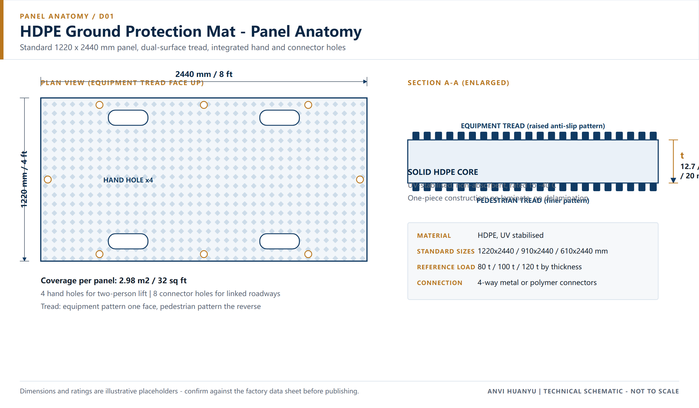
Three different products are routinely called “crane mats” in tenders. They are not interchangeable.
| Product | What it does | Typical construction | How it is verified |
|---|---|---|---|
| Ground protection / access mat | Spreads wheel loads, protects the surface, forms temporary roads and working platforms | HDPE panel, e.g. 1,220 × 2,440 mm, 12.7–20 mm | Published distributed load reference, subgrade assessment |
| Crane work platform / crane mat | Creates a larger, level, load-spreading area beneath a crane or under several supports | Timber bog mats, composite mats, steel or engineered layered systems | Engineered platform design based on ground investigation |
| Outrigger pad / outrigger float | Receives one concentrated leg reaction and spreads it to an allowable bearing pressure | Steel, engineered composite, UHMWPE or laminated timber pad | Rated capacity for a defined point load and support condition |
Our HDPE ground protection panels belong to the first row. They are useful around a lift — for the approach route, a levelled staging area, or an additional spreading layer under a properly specified pad — but they are not a substitute for row two or three. A 100 t crane does not distribute 100 t evenly over four legs: the maximum single-leg reaction depends on radius, counterweight, boom configuration, slew position and dynamic factors, and can be a large fraction of the total on one foot.
Point loading also changes how the board itself behaves. A wheel load is spread over a tyre patch and then over the panel; an outrigger float concentrates force into a small area near the centre of a panel, where the board bends between whatever supports it. A thicker board helps, but bending, effective contact area and the subgrade still govern.
When to use HDPE panels around a lift — and when they are not acceptable
Appropriate uses
- Temporary approach and positioning routes for the crane and its support vehicles.
- A levelled working platform for non-critical plant, subject to the ground assessment.
- A supplementary spreading layer beneath an engineered pad where the platform design calls for one.
- Ground protection so that the lift area can be reinstated without excavation.
Not acceptable
- Using a standard panel as the sole rated outrigger pad in a lift plan.
- Applying the published 80 / 100 / 120 t nominal ratings as point-load capacity.
- Stacking or double-layering panels without an engineer-approved configuration and documented capacity.
- Placing panels over voids, trenches, services or uncompacted backfill — panels are not temporary bridges.
- Lifting on saturated clay, peat or untested fill without a ground investigation and derating.
- Any case where the insurer, appointed person or national lifting code requires certified equipment.
The applicable lifting code is a matter for your jurisdiction and your appointed person — whether that is ASME B30.5 in the US, BS 7121 in the UK, or an equivalent national framework. Those documents govern the lift plan; a product page does not. We mention them so that the boundary is clear, not to claim any product certification against them.
How to calculate the bearing area an outrigger needs
This is the calculation a lift planner performs before any pad is selected. It is shown here as a worksheet with assumed inputs, not as a design service or a certified value.
Worksheet
| Symbol | Quantity | Where it comes from | Illustrative input |
|---|---|---|---|
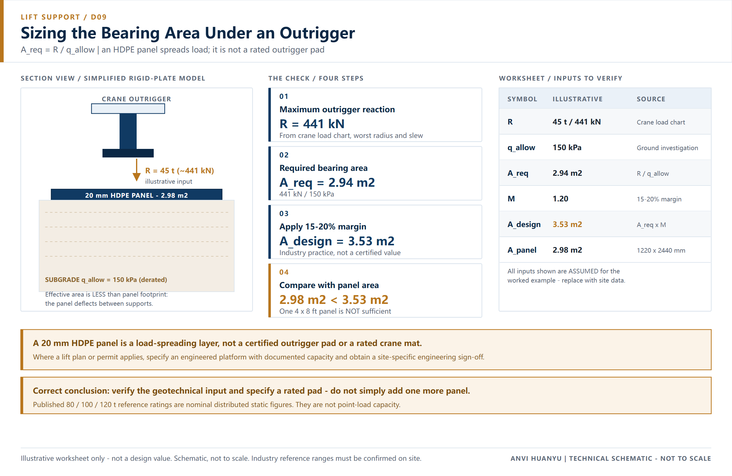
R | Maximum outrigger reaction | Crane load chart at the worst radius/slew, including counterweight and dynamic allowance | 45 t (≈ 441 kN) |
q_allow | Allowable ground bearing pressure | Ground investigation / geotechnical report, already derated for moisture | 150 kPa |
A_req | Required effective bearing area | A_req = R ÷ q_allow | 441 ÷ 150 = 2.94 m² |
M | Safety margin | Industry practice, 15–20% above the calculated case | 1.20 |
A_design | Area to provide | A_req × M | ≈ 3.53 m² |
A_panel | Area of one 4 × 8 ft panel | 1.220 × 2.440 m | 2.98 m² |
Reading the result: even in this simplified rigid-plate model, one 4 × 8 ft panel (2.98 m²) is smaller than the 3.53 m² needed after margin. In reality the effective area is smaller still, because an HDPE panel deflects between supports and the load is not spread uniformly to its edges. So the correct conclusion is not “add one more panel of the same thickness” — it is: verify the geotechnical input, specify an engineered pad or layered platform with a known rated capacity, and have the configuration signed off.
Sequence for the site file
- Obtain the crane load chart and identify the maximum single-outrigger reaction at the actual working radius and slew range.
- Obtain the ground investigation: allowable bearing pressure, groundwater, fill, buried services and any voids.
- Apply subgrade derating. Published industry guidance indicates saturated soil can lose 30–50% of the bearing capacity of dry compacted soil; peat and organic soils more.
- Compute
A_req = R ÷ q_allow, then apply a 15–20% margin. - Select a rated pad or engineered platform whose documented capacity covers the design case — including the bending case, not just compressive strength.
- Define the panel/pad arrangement and connection in the lift plan. If any stacking is proposed, it needs its own calculation and sign-off.
- Prepare and inspect the ground: level, compact, drain, and confirm support across the whole footprint.
- Document and retain: reaction calculation, ground report, product data, arrangement drawing, inspection record and sign-off. This is the file an insurer asks for after an incident.
A generic thickness chart cannot replace steps 1–3. Our specifications page gives the panel dimensions for layout drawings; our buying guide covers the commercial side. Neither is a lift plan.
What is at stake: a risk-based view of the benefits
We will not quote a invented accident cost. The economic argument is better made as a consequence table, because the numbers that matter are your own downtime, hire and insurance rates.
| Control measure | Consequence if omitted | Who carries the cost |
|---|---|---|
| Correct outrigger reaction calculation | Undersized bearing area; leg settlement during slew | Crane hire, programme delay, investigation |
| Ground investigation and derating | Bearing failure on wet or filled ground | Recovery, rework, possible injury |
| Rated pad / engineered platform | Panel bending or cracking under a concentrated load | Plant damage, lift abort |
| Documented arrangement and sign-off | Insurer or regulator cannot verify the lift | Claim exposure, stop-work order |
| Reusable HDPE access layer around the platform | Rutted approach, bogged support vehicles, reinstatement excavation | Site logistics and ground restoration |
Where HDPE panels do deliver measurable value around a lift is in the last row: a clean, dry, reinstatable approach and staging surface that can be recovered and redeployed. That is a real saving, and it is separate from the safety case for the lift itself. See HDPE vs steel mats for the handling and recovery comparison.
Why this mat — not a lighter panel or another material
| Option | Appropriate role near a lift | Why it is not the answer to a point load |
|---|---|---|
| 12.7 mm HDPE | Pedestrian and light-service-vehicle surfaces only | Deflection under a concentrated float is unacceptable; the lightest board is the wrong board here |
| 15 mm HDPE | Approach routes for light support vehicles on firm ground | Still a distributed-load panel, not a rated pad |
| 20 mm HDPE | Starting point for the working layer; approach and staging | It is the stiffest standard panel we list, but it remains a spreading layer |
| Engineered composite / steel pad | Receiving a defined outrigger reaction | Correct tool for the job; higher unit cost, known rated capacity |
| Timber bog mat / engineered platform | Soft ground, crawler cranes, very large footprints | Heavy, absorbs water, may need specialist placement |
| Plywood sheets | Nothing in a lift plan | Not rated, delaminates when wet, unpredictable — see HDPE vs plywood mats |
The question “why choose your panel at all?” has a narrow but honest answer: for the surrounding working area, because it is light, does not absorb water, is washable, does not corrode, and can be redeployed across many lifts. For the outrigger itself, choose a rated pad. Blurring those two roles is how specifications go wrong.
If a project needs a heavier-duty configuration, our heavy-duty panels are the relevant starting point for the surrounding platform — still subject to the calculation above.
Why 20 mm is only a starting point
The selection chain for a distributed load — vehicle weight → contact pressure → spread over the panel → subgrade derating → margin → thickness — does not transfer to a point load. Under an outrigger float, three extra effects dominate:
- Local bending. The panel acts as a plate on an elastic foundation. Its stiffness, and the distance to the nearest support, determine how much of the 2.98 m² is actually engaged. More thickness raises stiffness but does not make the whole board effective.
- Support condition. A panel over firm, uniform, compacted ground behaves very differently from one over a hollow, a trench or saturated clay. This is why the ground investigation comes before product selection.
- Configuration. A stacked or double-layer arrangement changes the load path entirely. It cannot be assumed to double capacity; it needs its own calculation and engineering sign-off.
Therefore:
- 20 mm is the minimum we would discuss for a working layer supporting crane logistics, and only after the calculation.
- We do not use the published 120 t nominal figure in lift calculations. Those ratings (80 / 100 / 120 t for 12.7 / 15 / 20 mm) are published reference figures for evenly distributed static loading on firm, level subgrade; they are not certified design values, not point-load capacities, and not permission to bridge voids. We publish no test method, sample thickness, support span or test report for these figures; they are labels, not design inputs.
- Thickness convention matters twice here. Confirm whether a quoted figure is the base sheet or overall height including raised tread, because the effective bending stiffness depends on the base sheet. See how to choose ground mat thickness.
- Where a lift plan or permit applies, obtain a site-specific engineering assessment. No product page, including this one, substitutes for it.
Common mis-specifications: reading a crane’s total tonnage as a per-leg load; assuming four legs share the load equally; treating “120 t” as a point-load rating; stacking panels without sign-off; and skipping the wet-weather derating.
Failure modes in lift support areas
| Failure | Visible sign | Cause | Control |
|---|---|---|---|
| Leg settlement during slew | Crane goes off level, load swings | Bearing area undersized for the peak reaction | Recalculate at worst slew; increase rated pad size |
| Panel cracking at hand holes | Star cracks from cut-outs | Concentrated load near a hand hole | Keep float bearing away from hand holes; use rated pad |
| Pumping over a void | Board flexes, water or fines rise | Uncompacted trench or service below | Ground investigation; never bridge voids |
| Stack slip | Layers shift under lateral load | Unengineered double layer | Sign-off and positive connection |
| Edge crush | Corner splits | Float placed near a panel edge | Layout drawing with load positions marked |
| Wet-ground creep | Gradual tilt over hours | Saturated subgrade, no derating | Drain, geotextile, derate, re-inspect |
What to verify with any supplier before you buy
For a lift-related enquiry, ask for documentation, not adjectives. Eight items belong in the file:
- The test method behind any stated load figure — static or dynamic, distributed or point, and the standard used.
- Sample thickness and support span at test, including whether the figure is base sheet or overall.
- Whether any point-load or outrigger-specific test exists at all; if not, the supplier should say so plainly.
- How will the layered platform be built and dismantled by hand, and is lifting plant available? Trial it with a sample panel; a nominal weight would not change the bearing-area calculation above.
- Material declaration and low-temperature behaviour, including whether any −40 °C claim has a published test basis.
- Thickness tolerance and batch traceability — a layered platform depends on consistent panels.
- Connector specification if any linked arrangement is proposed.
- A report with an identifiable issuing laboratory and report number, plus the warranty terms in writing.
If a bidder answers “our mat is rated 120 tonnes” and cannot answer item 1, that figure cannot enter a lift plan. Apply the same eight questions to every bidder, including us; a figure a supplier cannot document is not a design input.
Because a layered platform depends on every panel sitting flat, batch consistency matters more here than on any other page. We can supply current working photographs of a thickness check being taken on a finished panel, the production line in operation, and an export container being loaded when we quote. A photograph shows that an inspection takes place; it is not a tolerance figure, a batch record or a test report, and it must never be offered as evidence in a lift plan. The eight documents above remain the only acceptable basis for that decision.
Specification summary for the area around a lift
| Item | Position |
|---|---|
| Panel role | Approach route, staging and supplementary spreading layer only |
| Panel | 1,220 × 2,440 mm HDPE, dual-face tread, 4 hand holes + 8 connector holes |
| Thickness | 20 mm minimum for the working layer, after the bearing calculation |
| Outrigger support | Rated engineered pad or platform, not a standard HDPE panel |
| Calculation | A_req = R ÷ q_allow with 15–20% margin and subgrade derating |
| Stacking | Not permitted without engineering sign-off |
| Reference ratings | 80 / 100 / 120 t nominal, distributed static on firm level ground — not certified design values, not point-load capacity |
| Documentation | Load chart reaction, ground report, arrangement drawing, inspection record, sign-off |
Frequently asked questions
What thickness mat should go under a crane outrigger? Thickness alone is the wrong question. Calculate the maximum outrigger reaction and the allowable ground bearing pressure first, then specify a rated pad or engineered platform with the required effective area and a 15–20% margin. A 20 mm HDPE panel may form part of the surrounding working layer, but is not a rated outrigger pad.
How do you calculate outrigger point load? Take the maximum single-leg reaction from the crane load chart at the worst radius and slew, including counterweight and dynamic allowance. Convert to kN, divide by the allowable ground bearing pressure in kN/m² to get the required area, then apply a safety margin and derate for wet or weak subgrade. In our worked example, 45 t at 150 kPa requires 2.94 m² before margin and about 3.53 m² after.
Can I stack two ground protection mats for a lift? Not as a default. Stacking changes the load path and cannot be assumed to double capacity. Any stacked arrangement needs its own calculation, a defined connection between layers, and engineering sign-off in the lift plan.
Are HDPE mats approved for lift plans? Standard ground protection panels are not certified outrigger pads. They may be included in a lift plan as an approach or spreading layer if the appointed person and the applicable lifting code accept the arrangement and the documentation supports it. The rated pad under the leg is a separate specified item.
Can a mat listed at 120 t be used under a 100 t crane? No — that comparison is not valid. The 120 t figure is a nominal distributed static rating on firm level ground, while an outrigger is a concentrated reaction that may be a large fraction of the crane’s total on one small float. Compare the calculated leg reaction against a rated pad instead.
What is the difference between an outrigger pad and a ground protection mat? An outrigger pad is rated for a defined point load and support condition; a ground protection mat spreads distributed wheel loads over a wider area to protect the surface. They solve different problems and are often used together — the pad under the leg, the mats around it.
Get a thickness and panel count for your site
Send the crane model and load chart, maximum radius, calculated outrigger reaction, ground investigation result and lift duration. We will tell you honestly whether HDPE panels are appropriate for the surrounding area, and what we cannot supply — to albert@hdpegroundmat.com or via our contact page.